Risk assessments and reports regarding hazards associated with static electricity that result from a Hazop (hazard and operability study) are an effective way to find and identify processes and methods that can prevent ignition of a flammable atmosphere in the presence of static electricity.
The task of identifying the correct grounding solution falls to people like you and members of your team, and it is unlikely to be something you deal with on a daily basis. For most people, it is probably the type of project they will handle once or twice in their career. However, get it right the first time and it quickly becomes an area where you will benefit from the knowledge throughout your career. This guide is intended to help you find the right path and is best described as an introduction to the subject of static control in hazardous areas.
The guide is divided into three sections. The first part covers industry strategies that provide guidance on controlling static electricity in hazardous areas. The second part helps you develop the “best approach” for controlling electrostatic hazards in your workplace, and the third part addresses hazardous-area equipment—specifically what you should look for when selecting an EX-certified and approved grounding solution.
1. Benchmarks for static electricity grounding
Before you start reading this guide in order to specify and purchase static grounding solutions, it should be noted that certified equipment for hazardous areas, bearing the SIRA or BASEEFA mark, is not an approval of the system’s performance in providing static grounding protection.
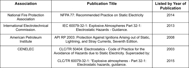
The committees tasked with developing and updating these guidance documents, in line with the latest technologies, are employed by companies and consultancies operating within the Ex industry. The recommendations described in these guidance documents will ensure that all electrostatic hazards present in your company’s operations are under your control. If you can specify grounding solutions that demonstrate compliance with the table on the left, you ensure that your static grounding protection methods reflect the latest technology for preventing fires and explosions caused by static electricity.
The guidelines in Table 1 describe how and why certain operations—whether involving liquids, gases, or powders—can generate static electricity and result in static charge accumulating on the equipment used in the process. The primary way to prevent ignition caused by static electricity is to ensure that all conductive and semi-conductive equipment, including people, is bonded and grounded to a verified grounding point for true earth. This ensures that electrostatic charges cannot accumulate on equipment and discharge a spark into an ignitable atmosphere. Because the earth has an infinite ability to balance positive and negative charge, if equipment is connected to it, that equipment is at “earth potential”, meaning it cannot become charged by material movement.
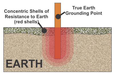
To ensure that equipment cannot accumulate electrostatic charge, it must be connected to the earth’s general mass using a true earth point. The resistance between the grounding point and true earth must be low enough to allow the electrostatic charge to pass down into the ground.
As with many other safety-related functions, benchmarks have been established. The minimum theoretical requirement for grounding electrostatic charges is commonly described in academic circles as having an electrical resistance not exceeding 1 megohm (1 million ohms) between the object and the earth’s general mass. However, it is known that metal objects at risk of charge accumulation, such as tankers, and grounding circuits that provide grounding protection should never show an electrical resistance of more than 10 ohms, if they are in good condition.
This 10-ohm value is the only resistance value consistently recommended in all publications listed in the table above. Therefore, wherever a grounding solution is required for processes involving metal objects such as weigh tanks, railcars, plates, drums, and containers, grounding systems that demonstrate earth monitoring values of 10 ohms or less should be specified.
Another reason the theoretical value of 1 megohm is irrelevant in practice is the requirements associated with grounding Type C FIBCs. Although CLC / TR: 50404 (2003) states that the resistance through a Type C FIBC bag should not exceed 100 megohms, the latest guidance published in IEC 60079-32-1 (2013) and NFPA 77 (2014) states that the resistance through the bag must not exceed 10 megohms. It is clear that a “theoretically acceptable” value of 1 megohm is impractical in the context of metal objects that should show a reference resistance of 0 to 10 ohms or less, and Type C FIBCs that should show benchmarks of either 0 to 10 megohms or 0 to 100 megohms (depending on which standard the bag complies with).
NOTE! If you are purchasing a grounding solution for Type C FIBC bags, you must ensure that you know which standard the bags comply with. If you do not know which standard the bag complies with, consult the supplier. Once you have the correct information, you should invest in a Type C FIBC grounding system that monitors the grounding circuit from 0 ohms up to 10 megohms (NFPA 77 / IEC 60079-32 compliant) or from 0 ohms up to 100 megohms (CLC / TR: 50404 compliant). Avoid a system that does not monitor the full resistance range, as it is likely to fail bags designed to operate up to 100 megohms and pass bags that should only operate up to 10 megohms.
2. Finding the right grounding solution
Your company’s Hazop report will identify the risk of static sparks from specific equipment such as rail tankers, drums, etc., and provide an assessment of the impact that a fire or explosion caused by electrostatic ignition could have on the area. It will be your responsibility to determine what the grounding solution needs to look like. Before you begin the search for a static grounding solution, determine the layers of protection you want against an electrostatic ignition risk. The more layers used to protect against an ignition source, the more likely static electricity will be controlled in a safe, repeatable, and reliable manner. Answering the following questions will help you identify the protection classes you need from your static grounding solution: a. Who is responsible for grounding the equipment before and during operation, and how do we inform them that there is a risk of electrostatic discharge? b. If the equipment, for any reason, loses its grounding protection during operation, do I want the process to continue building up electrostatic charge on the equipment? c. What type of equipment requires static grounding protection, and does it have unique characteristics that require a specific type of grounding solution?

2.1 Assessment of the necessary layers of protection in relation to question a:
With the exception of locations such as laboratories that handle small quantities of flammable products, responsibility for grounding equipment identified as a static discharge risk will lie with the equipment operators, or in the case of tankers and vacuum trucks, the vehicle driver. Because static electricity is a complex subject, it can be difficult for people who do not deal with it daily to understand the fundamentals of why it is a serious risk in a flammable atmosphere. The attitude of “it cannot happen to me” can accompany this lack of awareness, especially when there is no tangible hazard or visual risk that would trigger a natural safety-related action from an individual.
As it is not a visible or tangible hazard, the greatest challenge is getting your company’s personnel to take responsibility for their own safety and the safety of their colleagues. The most effective way to establish grounding procedures is to install a grounding solution that requires visual confirmation of a safe condition before a process can begin. If the operator has a visual reference point to know when the operation can start, they can be trained to take responsibility for grounding the equipment they use. The most effective indication method is to use green indicators to communicate a “GO” condition and red indicators to communicate a “NO GO” condition. To draw better attention to indications, pulsing LED lights can be very effective in communicating to the operator that the resistance in the grounding circuit is continuously monitored and that they need to see a pulsing green light before and throughout the entire process.
Some grounding solutions have a built-in buzzer that can warn the operator of a lost grounding connection, but caution should be exercised when evaluating such equipment. The audible signal from a buzzer often becomes difficult to hear when competing with noise in the work environment, or if the operator is wearing hearing protection or earplugs. The benchmarks that should be in place for monitoring grounding and bonding circuits should be based on the guidelines described in the publications listed in the table above.
This will ensure that your grounding solutions comply with laws and regulations and align with the latest standards. In summary, metal-constructed equipment such as rail tankers, railcars, drums, and powder handling systems should be monitored with a resistance not exceeding 10 ohms to a verified grounding point.
2.2 Assessment of the necessary layers of protection in relation to question b:
Visual indication and continuous grounding circuit monitoring are two fundamental protection classes that tend to go hand in hand. However, when there is no active grounding of the equipment and the operation is still running, additional controls must be in place to prevent the equipment from rapidly accumulating dangerous electrostatic charges. Stopping the movement of the material being handled will stop the generation of static electricity. One measure is for the operator to press an emergency shutdown button to prevent further generation and accumulation of static electricity on the equipment they are using. People’s attention and focus may shift to other activities while the operation is in progress, and if grounding or bonding is lost, there is an additional safeguard that can shut down the operation automatically.
Automatic shutdown can be achieved with grounding systems that have output contacts that can be connected to a range of devices (switches, valves, PLCs), which can then perform a shutdown in response to the monitoring circuit identifying a lost earth connection. Visual indication is an effective safeguard for verifying grounding before the process is started by the operator. The system’s potential-free auxiliary contacts can also be used to automatically shut down the operation or activate external warning systems. Unlike a manual shutdown, this prevents rapid build-up of static electricity.
2.3 Assessment of the protection classes required in relation to question c:
As mentioned earlier, there are many processes that require static grounding protection, but the type of process and the environments in which they are carried out can vary greatly. Different zones, combined with execution and risk—particularly the amount of flammable or combustible material at risk of ignition—can influence the selected solution.
This generally means that a “one-size-fits-all” solution will not provide the levels of protection and installation flexibility you may need. The following examples help illustrate how different processes can have unique characteristics that may influence the type of grounding solution used by your company.
2.3.1 Vessels
The process of filling vessels is continuous, and the vessels can be filled from fixed pumps (which can fill four vessels simultaneously), from fixed pumps on a roller conveyor system, or from portable pumps. As such operations are typically carried out indoors, a range of Ex environments—from Zone 0 through to non-hazardous areas—can reflect a spectrum of installation options and required protection levels that are ideally suited to your static grounding application.
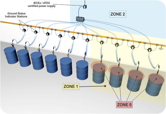
Imagine a scenario where up to 10 vessels are to be filled from portable pumps at the same time and location. Because the pumps are controlled by the operators, they are required to continuously monitor the liquid level in the vessel. Compared with connecting the pumps to a central system, the operators must both start and stop the pump in response to a visual indication of each vessel’s grounding connection. In such a process, Bond-Rite® REMOTE can monitor multiple vessels from a single power supply around the clock.
The advantage of this type of solution is that it bridges the gap between having no visual indication via “passive” grounding clamps and simple grounding systems, and junction-box solutions that require a 230 V AC supply or 24 V DC connected to 10 separate grounding systems. A solution such as Bond-Rite® REMOTE, which only requires a 230 V AC or 24 V DC supply to its Zone 2/21 unit, can safely deliver power to the indicators in Zone 10 with 0/20 ground status and can then independently monitor the grounding status of each individual vessel. If filling is performed less routinely, installation time can be reduced by using an LED indicator powered by its own internal battery.
2.3.2 Vacuum trucks
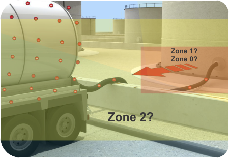
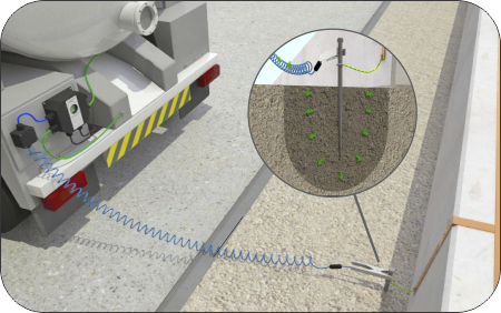
Vacuum trucks provide a range of services in hazardous environments, with the primary role of cleaning out storage tanks and vacuuming up spills from leakage incidents. They also present one of the most complex challenges when it comes to protecting against electrostatic hazards in a safe and repeatable manner. They process and transport large quantities of flammable liquids and powders, often under difficult conditions when it comes to controlling the presence of flammable atmospheres. They operate in many different locations, often at temporary worksites where there are no monitoring systems, which increases the risk of voltage generation. In short, the risks are very high, and until not long ago all drivers could do was connect a passive grounding clamp to a metal object (such as a tank shell or pipeline), hoping they could ground the truck in a safe, reliable manner. This was done without monitoring the grounding circuit and without knowing whether the object connected to the clamp had a verified true earth connection (see image on the right).
Today, vacuum truck service providers and their customers can use truck-mounted grounding systems that verify a connection to true earth; monitor the connection throughout the process; provide a visual indication of a verified earth; and automatically shut down the operation if the earth connection is lost during transfer. Due to the risk of this type of operation, a solution such as Earth-Rite® MGV can offer maximum protection by ensuring that:
1. The grounding point the truck is connected to is also connected to a true earth point.
2. The driver has a visual indication of a good static grounding connection.
3. The connection between the truck and the verified grounding point is continuously monitored down to 10 ohms.
4. The process is stopped if the earth connection is lost—particularly important when the driver does not have constant visibility of the indicators.
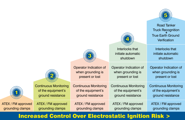
To find the best-fit solution, try to identify one where you can combine the features described in the columns on the left. At the most basic level, you should avoid using devices such as welding clamps and alligator clips, as they are not designed with static grounding in mind (especially for tasks that require penetration of an insulating layer such as paint coating or rust). Static grounding clamps should undergo FM testing to ensure they are suitable for use in hazardous areas. Thereafter, the specified grounding solution should combine the features shown in the image on the left.
Selecting certified equipment for hazardous environments
Try to find equipment that has been approved to standards that reflect the latest technology for hazardous areas, in accordance with IECEx and EN standards. It is worth noting that all standards (IEC 60079 standards for explosive atmospheres) used to evaluate equipment for ATEX are produced by the International Electrotechnical Commission on behalf of CENELEC. There are many ATEX-certified devices on the market today—not only grounding devices—that were approved to standards that have undergone multiple revisions or no longer exist since the devices were first approved.
For example, the current standard for intrinsically safe equipment, EN 60079-11 (2012), has undergone two revisions since 2002, with the major revisions released in 2007 and 2012 respectively. It is very likely that a grounding system approved before 2007 would need to be redesigned to meet the requirements of EN 60079-11 today.
Summary
This guide will hopefully provide you with sufficient information to help you find a static grounding solution that best fits your company’s operations and risk profile. The basis of your purchase specification should be built on:
– Static grounding equipment that complies with the latest technology in static control, namely IEC 60079-32-1, CLC / TR: 60079-32-1, NFPA 77 and API RP 2003. – Determining the levels of protection you believe will influence the risk of electrostatic ignition—this will help you identify a grounding solution that best suits your processes and operators.
This article is the copyright of Newson Gale – ©Copyright Newson Gale 2019.