General and Planning
Electrical equipment should, as far as possible, be placed outside hazardous areas. Accumulation of dust, condensate, or sublimate from explosive substances on electrical equipment, especially on those with hot surfaces, must be avoided. The electrical installation must be planned and executed in such a way that the risk of mechanical damage or chemical or thermal attack is minimized. Electrical equipment placed outside hazardous areas but above zone E1 or zone E2 must be designed to prevent the risk of falling objects, such as light sources or parts thereof, from the equipment. Planning should also consider the need for periodic inspection, care, and maintenance. The need for backup power should be considered for parts of the facility that must remain operational during a mains power failure.
If flammable goods are present together with explosive goods, the hazardous area may also need to be classified according to SS-EN 60079-10. In such cases, the electrical installation must also comply with the requirements of SS-EN 60079-14. Certain electrical equipment is permitted with explosion-protected design according to SS-EN 60079-0 and SS 421 08 19 or equivalent design, regardless of whether the area is also classified as a hazardous area with an explosive gas mixture or not. This electrical equipment must then be installed according to SS-EN 60079-14. If combustible dust is present together with explosive goods, the hazardous area may also need to be classified according to SS-EN 61241-10. In such cases, the electrical installation must also comply with the requirements of SS-EN 61241-14.
Certain electrical equipment is permitted for use in the presence of combustible dust with a design according to SS-EN 61241-0, regardless of whether the area is also classified as a hazardous area with an explosive dust-air mixture or not. This electrical equipment must then be installed according to SS-EN 61241-14. For the selected electrical equipment to maintain its intended protection against ignition of the explosive substance or its surroundings, the installation instructions and any special conditions for the electrical equipment must be met. For certain types of machinery and apparatus, special requirements also apply; read more here.
Selection of Electrical Equipment
For the selection of appropriate electrical equipment, information is required regarding:
– zone classification of the hazardous area (for electrical equipment in storage not in permanent use, see the following article)
– ignition temperature or temperature class of the explosive substance
– ambient temperature
– other external influences.
NOTE 1 – Regarding classification, reference is made to SS 421 08 24.
NOTE 2 – Other external influences refer to:
– the risk of liquid or dust other than explosive dust entering the electrical equipment,
– the risk of mechanical damage, vibrations, or chemical or thermal attack.
Selection with regard to Zone Classification
For the selection of electrical equipment in the different zones, the following applies:
Electrical equipment in zone E1:
electrical equipment with enclosure class IP 6X
electrical equipment corresponding to the following explosion-protected designs:
Exi – according to SS-EN 60079-11 or SS-EN 60079-25 and with intrinsically safe apparatus with enclosure class IP 5X,
Exm – according to SS-EN 60079-18 and with any junction box with enclosure class IP 6X
Exp – according to SS-EN 60079-2 with continuous flow, with both supply and exhaust air ducts and with electrical equipment and ducts in enclosure class IP 5X,
Exs – according to SS 421 08 19 if the design is encapsulated or has equivalent tightness against dust ingress and with any junction box with enclosure class IP 6X.
In Exp design, the protective gas (generally air) can also be used for cooling the electrical equipment so that its surface temperature is lower.
NOTE – Regarding the installation of electrical equipment for areas with explosive gas mixtures, see SS-EN 60079-14.
electrical equipment for use in the presence of combustible dust corresponding to the following designs:
Ex tD – according to SS-EN 61241-1 and with enclosure class IP 6X,
Ex maD – according to SS-EN 61241-18 and with any junction box with enclosure class IP 6X.
NOTE – Regarding the installation of electrical equipment in the presence of combustible dust, see SS-EN 61241-14.
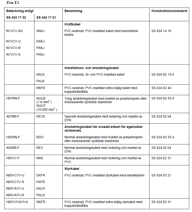
cable for fixed installation with metal sheath, metal screen, or concentric conductor and sheath protection of
insulating material
cable with copper wire braid and with outer sheath of insulating material
heavy-duty connecting cable with sheath of polychloroprene or equivalent synthetic elastomer
special connecting cable with EPR insulation and sheath
normal connecting cable with sheath
– of polychloroprene or equivalent synthetic elastomer,
– of EPR, or
– of PVC
when the connecting cable is used for intrinsically safe circuits.
NOTE – The above indicates that wiring systems with basic insulated conductors in conduits are not permitted.
Examples of cables according to Swedish standards are given in the cable types section.
Certain exceptions to the cable selection requirements are specified in the cable types section.
Heating cables may not be installed in zone E1. Electric fan heaters (aerotempers) may not be placed in or used for blowing into zone E1. Other electric heating apparatus for space heating may not be placed in zone E1.
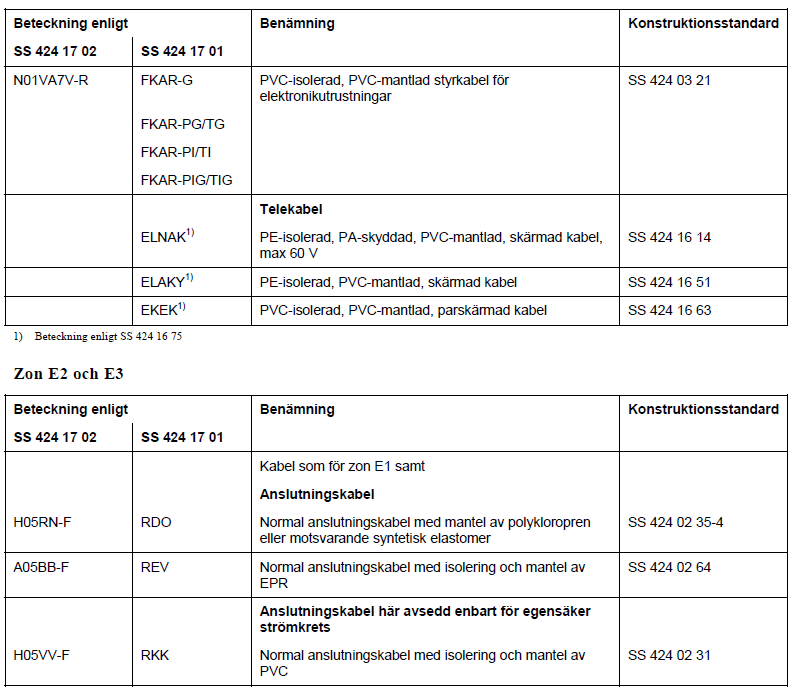
Electrical equipment in zone E2:
– electrical equipment as in zone E1
– electrical equipment with enclosure class IP 4X
– electrical equipment with enclosure class IP 34, when the equipment is under constant supervision during operation or use
– electrical equipment with explosion-protected design corresponding to SS-EN 60079-0 – with the exception of design Exo – or SS 421 08 19 and installed according to SS-EN 60079-14
– electrical equipment for use in the presence of combustible dust, design corresponding to Ex mbD according to SS-EN 61241-18 and with any junction box with enclosure class IP 4X and installed
according to SS-EN 61241-14
– normal connecting cable with sheath of polychloroprene or equivalent synthetic elastomer or of EPR, see also the cable types section
– heating cable corresponding to self-limiting type with metal sheath or metal screen.
The Swedish Electrical Safety Authority’s regulations ELSÄK-FS 2004:1, Chapter 1, § 5, permit – under certain conditions – deviations from Swedish standards if adequate safety for persons and property is nevertheless achieved. The assessments forming the basis for the chosen design must be documented. If deviations from Swedish standards – equivalent to the enumeration below – are deemed necessary, it is assumed that the responsible party ensures that there is no risk of ignition of the explosive substance or other material. In this regard, the electrical equipment should be under constant supervision when in use. There should also be written consent from the responsible party identifying the electrical equipment.
Electric fan heaters (aerotempers) may not be installed in zone E2.
Electric fan heaters for blowing into zone E2 must be arranged and designed according to the section: Electric Machines
Other electric heating apparatus for space heating must be arranged and designed according to the section: Transformers.
Electrical equipment in zone E3:
– electrical equipment as in zone E2, fixedly installed and only for the following purposes:
1. lighting and outlets
2. alarms
3. sprinkler system
4. lifting equipment (hoist or similar)
5. gate control
Storage not in permanent use
This refers to storage of less than 100 kg of pyrotechnic articles, not in permanent use (maximum two months per year), e.g., for the sale of recreational fireworks.
For the selection of electrical equipment in the aforementioned storage areas, the following applies:
– the rules for zone E3, as above, or:
– electrical equipment, designed and arranged according to the Electrical Installation Regulations SS 436 40 00 section 422.3 for areas with increased fire risk, fixedly installed and only for the following purposes:
1. lighting
2. alarms
3. heating
Heating cables are not permitted.
Electric fan heaters (aerotempers) may not be installed in the storage areas referred to here. Electric fan heaters for blowing into storage areas must be arranged and designed according to the section Electric Fan Heaters.
Other electric heating apparatus for space heating must be arranged and designed according to the section Other Electric Heating Apparatus.
Selection with regard to Ignition Temperature or Temperature Class and the Electrical Equipment’s Maximum Surface Temperature
Zone E1:
Information on the electrical equipment’s maximum surface temperature as stated below shall apply under the conditions specified in the design and testing standard for the respective electrical equipment. See also the section Maximum Surface Temperature
The maximum surface temperature of accessible parts of the electrical equipment must not exceed the values below, regardless of the ambient temperature:
For explosive substances within temperature class ET 1, the surface temperature of the electrical equipment may not exceed 120 °C during normal operation.
For explosive substances within temperature class ET 2, the surface temperature of the electrical equipment may not exceed 2/3 of the actual explosive substance’s ignition temperature during normal operation.
Zone E2, zone E3, and storage areas according to the section Storage not in permanent use:
The ignition temperature of the explosive substance does not need to be considered. For electrical equipment with a surface temperature above 100 °C, special protective measures are required to prevent the occurrence of fire. See, among others, the article: Special instructions for certain types of machinery and apparatus
Selection with regard to other external influences
In addition to the design or enclosure requirements specified in the “Selection of Electrical Equipment” section, the electrical equipment must have an enclosure or other protection considering environmental influences. Such influences may include, for example, the risk of dust (other than from explosive substances) or liquid entering the electrical equipment, with the risk of mechanical damage or chemical or thermal attack. In hazardous areas, high demands are placed on cleaning. Where this is done using water flushing, the enclosure class or installation of additional protection must also be chosen with this in mind. Electrical equipment is normally not designed for protection against ingress of liquid from high-pressure flushing units. In premises where high-pressure flushing is used, the electrical equipment must therefore be protected against such flushing by its location or other arrangement. Consideration must also be given to the risk of mechanical damage due to vibrations or other movements in the manufacturing process. When ordering electrical equipment, requirements for the enclosure class should be specified. See the section Enclosure Class.
Selection with regard to Ambient Temperature
The electrical equipment must be designed for use in the actual ambient temperature. NOTE – For electrical equipment that is not explosion-protected, the manufacturer’s information on the maximum permissible ambient temperature may need to be obtained. Explosion-protected electrical equipment is, unless otherwise stated on the equipment’s nameplate or in the certificate, designed for ambient temperatures between -20 °C and +40 °C. Connecting cables with PVC insulation or PVC sheath may not be used for movable or portable items where the ambient temperature can normally fall below +5 °C.
Disconnection
Electrical equipment whose continued operation during a disturbance could lead to an increased risk, such as the spread of fire, must be able to be disconnected from a location outside the hazardous area. Such disconnection can be done with the electrical equipment’s normal operating switch, if it is located outside the hazardous area. Electrical equipment whose continued operation is necessary to limit risks during a disturbance must have its own disconnecting device. Electrical equipment used only during the handling phase, such as unblocked outlets, must be disconnected after work is completed. In the wiring to electrical equipment in a hazardous area, all phase conductors must always be able to be disconnected, thus also in group wiring with only two phase conductors.
When working on a plant component, it should be noted that the neutral conductor is normally not disconnected during disconnection and can therefore carry sufficient voltage to earth (e.g., due to voltage drop, unbalanced load, or fault) to cause a spark upon contact with an earthed object. Primarily, work should be carried out when there is no risk of ignition of explosive substances, in which case the neutral conductor does not need to be disconnected. If work is carried out on a plant component when such a risk exists, the neutral conductor must also be disconnected. Regarding other measures to be taken on a plant before work, see the article: Inspection, control, etc.
Protective Measures for Mechanical Ventilation
Mechanical ventilation can be a condition for classification. Mechanical ventilation can mean that a room, space, or area is classified as a zone with a lower degree of risk than would be the case if mechanical ventilation were not present, or as a non-hazardous area. SS 421 08 24 states that faults in the ventilation system must be indicated by monitoring the flow in the exhaust duct and signaling ventilation failure. Furthermore, it states that ventilation failure should be considered, for example, by disconnecting electrical material that does not meet the requirements for the explosive atmosphere that arises during ventilation failure, or by interrupting operations. It also states that the consequences of ventilation failure must be considered before reconnecting electrical equipment. In case of risk of operational disturbances due to ventilation failure and subsequent disconnection of certain electrical equipment, backup operation for ventilation should be arranged. Before reconnecting electrical equipment after ventilation failure, the following measures must be taken: remove any release from the source of risk assess whether there was a risk of release entering the electrical equipment. If such a risk existed, the interior of the electrical equipment must be inspected and necessary cleaning carried out. If the electrical equipment’s enclosure is opened, it must be disconnected according to the provisions in the Swedish Electrical Safety Authority’s regulations ELSÄK-FS 2006:1, § 6. Necessary measures must be specified in the operating instructions.
System Earthing
The risk of ignition due to faults in electrical equipment can be reduced by limiting the magnitude and duration of the earth fault current in the installation. In addition to the limitation achieved by normal short-circuit protection in systems with a directly earthed neutral point, the earth fault current can be limited
by using earth fault sensing devices or systems with a non-directly earthed neutral point. The use of a non-directly earthed neutral point is limited to, for example, industrial installations where insulation is carefully monitored. Compare Electrical Installation Regulations SS 436 40 00, including sections 413.1.5 and 531.3.
This section shall not apply to intrinsically safe circuits. For such circuits, section 12 of SS-EN 60079-14 primarily applies.
– NOTE – Internationally, the following terms are used:
directly earthed system TN
non-directly earthed system IT
combined neutral and protective conductor PEN
protective conductor PE
neutral conductor N
Distribution systems with directly earthed neutral point:
Within hazardous areas, only TN-S systems may be used, meaning a separate protective conductor is required even in the main power system wiring. Separation of the neutral conductor and protective conductor must therefore occur in a central unit outside the hazardous area.
In addition to protection required by the Electrical Installation Regulations SS 436 40 00, Chapter 43 – Protection against overcurrents, for larger installations, a device should be present that automatically disconnects the plant component if the earth fault current exceeds 4 – 5 A. Such a device can help reduce the risk of breakdown and reduce stress on, for example, motors.
Distribution systems with non-directly earthed neutral point
If a system with automatic, selective disconnection in case of earth fault is chosen, the system should be applied to the entire distribution system, i.e., also to those plant components located outside the hazardous area.
If the system without automatic disconnection (signal only) in case of earth fault is chosen, special consideration must be given to the following:
– the system is only suitable for installations of limited extent, to which motors or consuming apparatus with high insulation and relatively high power are connected
– the installation is designed to prevent the occurrence of insulation faults as far as possible
– the system requires careful monitoring and continuous inspection of insulation
– the installation is under careful and professional supervision, and
– any fault that occurs is located and repaired as soon as possible.
NOTE – Compare with Electrical Installation Regulations SS 436 40 00 section 413.1.5.
Equipotential Bonding
Equipotential bonding must be carried out within hazardous areas to avoid dangerous sparking between metallic structures. Metallic structures that are in good metallic connection with each other, forming an unbroken path for current to earth, normally only need to be connected at one point to earth. For larger structures, several connection points may be needed. Within zone E1, metallic enclosures for electrical installation components must be connected with a special conductor to the equipotential bonding system, even if protective earthing of exposed parts is required according to the Electrical Installation Regulations SS 436 40 00. Within zones E2 and E3, no special connection to the equipotential bonding system is required if the exposed part is protectively earthed according to the Electrical Installation Regulations SS 436 40 00. Smaller electrical apparatus that have good metallic connection with process vessels, pipelines, etc. (e.g., thermal sensors, flow sensors, and pressure sensors) do not need to be connected by a special conductor to the equipotential bonding system if the process equipment is connected to this system. The equipotential bonding system must also be connected to the earthing electrode of the power system. Equipotential bonding conductors for purposes other than merely preventing electrostatic charging of objects with conductive or semiconductive surfaces should be insulated and have a conductivity at least equivalent to 10 mm2 Cu. For connecting smaller electrical apparatus, the cross-sectional area for short conductors may be reduced to 4 mm2 Cu. Equipotential bonding conductors may be marked with the color combination green and yellow. Otherwise, reference is made to SS 421 08 22. NOTE – Compare with SEK Handbook 433.
Cathodic Protection
Cathodic protection may not be installed in zone E1. Cathodic protection for metal parts may be used in zones E2 and E3 only if the protection is specifically designed for this purpose. Compare with section 6.7 in SS-EN 60079-14. NOTE – Cathodic protection systems are covered in SS-EN 50162.
Cables
When using single-core cables, consideration must be given to the risk of dangerous voltage or current in the metal sheath of the cables. See Electrical Installation Regulations SS 436 40 00 section 521.5. Cable Types Examples of cables with design according to Swedish standards for use in the different zones: NOTE 1 – Equivalent cables – corresponding to the enumeration below – may be used. Designs that completely or partially deviate from Swedish standards must, from an electrical safety perspective, meet the requirements of Swedish standards for the corresponding cable type. This must be verifiable. NOTE 2 – Regarding specific and general requirements stated in this standard, see section 1.
In addition to protection required by the Electrical Installation Regulations SS 436 40 00, Chapter 43 – Protection against overcurrents, for larger installations, a device should be present that automatically disconnects the plant component if the earth fault current exceeds 4 – 5 A. Such a device can help reduce the risk of breakdown and reduce stress on, for example, motors.
Distribution systems with non-directly earthed neutral point
If a system with automatic, selective disconnection in case of earth fault is chosen, the system should be applied to the entire distribution system, i.e., also to those plant components located outside the hazardous area.
If the system without automatic disconnection (signal only) in case of earth fault is chosen, special consideration must be given to the following:
– the system is only suitable for installations of limited extent, to which motors or consuming apparatus with high insulation and relatively high power are connected
– the installation is designed to prevent the occurrence of insulation faults as far as possible
– the system requires careful monitoring and continuous inspection of insulation
– the installation is under careful and professional supervision, and
– any fault that occurs is located and repaired as soon as possible.
NOTE – Compare with Electrical Installation Regulations SS 436 40 00 section 413.1.5.
Mineral-insulated, metal-sheathed cable with sheath protection of insulating material may be used as an installation cable for fixed wiring. Coaxial cable for high-frequency transmission with an outer sheath of insulating material with a nominal wall thickness of at least 0.75 mm may be used in hazardous areas, provided that the cable is not simultaneously used for power supply to, for example, amplifiers. The outer screen should be connected to the equipotential bonding system or the power system’s earthing electrode at only one point. The fire propagation class of cables must be at least F2 according to SS 424 14 75 unless otherwise specified. Exceptions to cable requirements may be made in the following cases: metal sheath, metal screen, or concentric conductor may be omitted on cables in or on machinery where adequate mechanical protection has been achieved by other means, see SS-EN 60204-1 cables may have a different design where required if they are fixedly connected to electrical equipment that complies with the requirements of the relevant zone and if they are made as short as possible and protected against external influences.
Installation
Control cables and other cables important for the safety of the installation, e.g., during disturbances, should be laid so that the influence from other plant components is minimized.
Cables must be laid so that their metal casing does not come into contact with structural parts made of conductive material. The insulation provided by the cable’s outer insulated sheath is generally sufficient to avoid such contact.
Where insulated cables accumulate, measures must be taken to prevent fire from spreading along the cables. Such measures may include using cables with a high flammability class, embedding cables in
non-combustible material, sealing penetrations to the same fire resistance class as the building component, arranging fire detection and extinguishing systems, etc.
NOTE – Regarding the requirement for sealing penetrations to the same fire resistance class as the building component, see Electrical Installation Regulations SS 436 40 00 section 527.2.
In cable ducts, trays, and similar, measures must be taken to prevent the accumulation of dust, vapor, condensate, or sublimate.
When cables are routed from one zone to another or from a zone to a non-hazardous area, and the boundary is formed by a building component, the penetration must be sealed to prevent the zone from extending beyond such a boundary.
To avoid damage to PVC-sheathed cables, caution must be exercised during installation at temperatures below 0 °C. If the cable temperature falls below -10 °C, special measures must be taken.
Connection of Cables
When connecting a cable to a plant component, it must be ensured that the enclosure class of the plant component is maintained. For the connection of electrical equipment for areas with explosive gas mixtures, reference is made to SS-EN 60079-14, and for the
connection of electrical equipment for use in the presence of combustible dust, reference is made to SS-EN 61241-14.
Certain plant components are provided with a label indicating that the temperature of the cable in the connection area may be higher than normal at the component’s rated load. In such cases, a cable intended for the temperature in question must be selected.
For the connection of mineral-insulated cables, connection accessories intended for such cables must be used. Connection accessories must ensure, among other things, that moisture cannot penetrate the cable’s insulating material and that the metal sheath is protectively earthed.
Electrical Protection
The electrical protection devices must be arranged so that automatic restart of the electrical plant component in question does not occur after tripping due to overload, overtemperature, short circuit, or earth fault. Measuring devices may have automatic reset.
Documentation
The following documents must be available at the facility, stored securely, and easily accessible for inspection:
– documents showing the classification of hazardous areas
– documents showing the type and routing of cables in the ground that affect hazardous areas
– documents for electrical equipment with explosion-protected or other designs, such as approval documents, documents containing special conditions for installation and use, other assembly, use, and
maintenance instructions, and documents on enclosure class and maximum surface temperature.
Identification of Plant Component
If a plant component must be placed so that its marking can only be read with difficulty or not at all, an additional nameplate must be affixed in a clearly visible location on or next to the plant component. Fastening an additional nameplate to explosion-protected electrical equipment may not be done without the manufacturer’s written approval.
Warning Signs
Warning signs must have Swedish text. The signs are designed with regard to applicable Swedish standards. See also AFS 1997:11. For electrical equipment with signs in a language other than Swedish, it must be ensured that the necessary supplementation with Swedish text is provided.
SEK Swedish Electrotechnical Standard